Deflection Head Track Overview
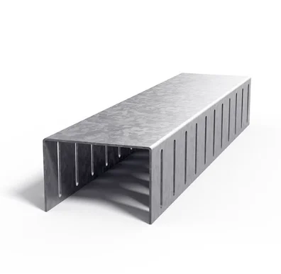
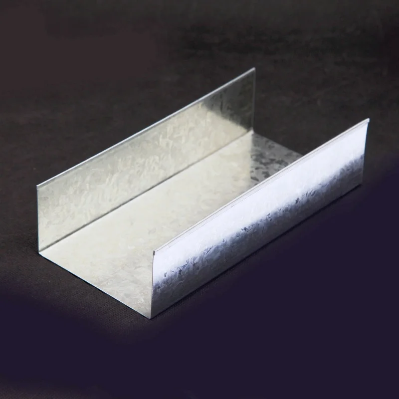
Deflection head track is used in walls that require vertical deflection from the ceiling. It provides a track at the head of the wall assembly for applications where the wall-to-ceiling connection needs to accommodate vertical deflection. The product is available in BMT options from 0.55 to 1.15, with the specific choices and corresponding profile sizes listed in the specifications below.
For project planning, confirm the selected track size and BMT against the requirements of the wall system and the details shown in the project documentation. The track is a component of a wall assembly, so its suitability depends on how it is specified and installed within that assembly. Reviewing the available sizes before ordering can help coordinate the head-track selection with the intended wall layout and the needs of the installation.
The product information identifies the track’s purpose and available manufacturing options without assigning a load rating or a movement capacity. Where project-specific performance criteria apply, use the relevant design and installation requirements to select the appropriate option. This keeps the product choice aligned with the intended application without assuming a specification that is not provided here.
Material and Construction
The stated material is galvanized strong steel, grade DX51D, with zinc coating listed as 120-275g. This information identifies the steel material and coating range provided for the product. The coating specification is presented as supplied and is not converted here into a different unit or interpreted as a separate performance guarantee.
A consistent material description can support straightforward product review when preparing a bill of materials, comparing specified options, or coordinating the track with other wall-system components. Refer to the project requirements when confirming material acceptance, handling, and installation practices. The listed material information should be considered together with the selected dimensions and BMT rather than in isolation.
For maintenance and application planning, keep the product identification and applicable project records available so that the installed component can be checked against the specified selection. The supplied details do not state a maintenance interval, service-life figure, or additional coating treatment, so those requirements should be established from the project documentation where applicable.
Available Sizes and Specifications
The specification table shows five profile sizes. Each listed size is available in the same four BMT options, and every size shown has a listed length of 3000mm. Use the table to identify the stated combination required for ordering and to coordinate the selected profile with the planned wall details.
| Size | BMT | Length |
| 51x50mm | 0.55/0.70/0.75/1.15mm | 3000mm |
| 64x50mm | 0.55/0.70/0.75/1.15mm | 3000mm |
| 76x50mm | 0.55/0.70/0.75/1.15mm | 3000mm |
| 92x50mm | 0.55/0.70/0.75/1.15mm | 3000mm |
| 150x50mm | 0.55/0.70/0.75/1.15mm | 3000mm |
The listed size and BMT are selection details, not interchangeable descriptions. Check both fields when preparing a purchase order or material schedule, particularly where more than one profile size or thickness is being used on a project. The 3000mm length is shown consistently for all five options in the supplied table.
Packing, Loading and Accessories
The product images identify the item as deflection head track and show the packing description as 10pcs/bdl. Use this stated bundle information when planning material quantities, receiving, and on-site organization. The product visual and packing visual are included below for reference; confirm order quantities against the selected size and BMT options.

Deflection head track

10pcs/bdl
Loading
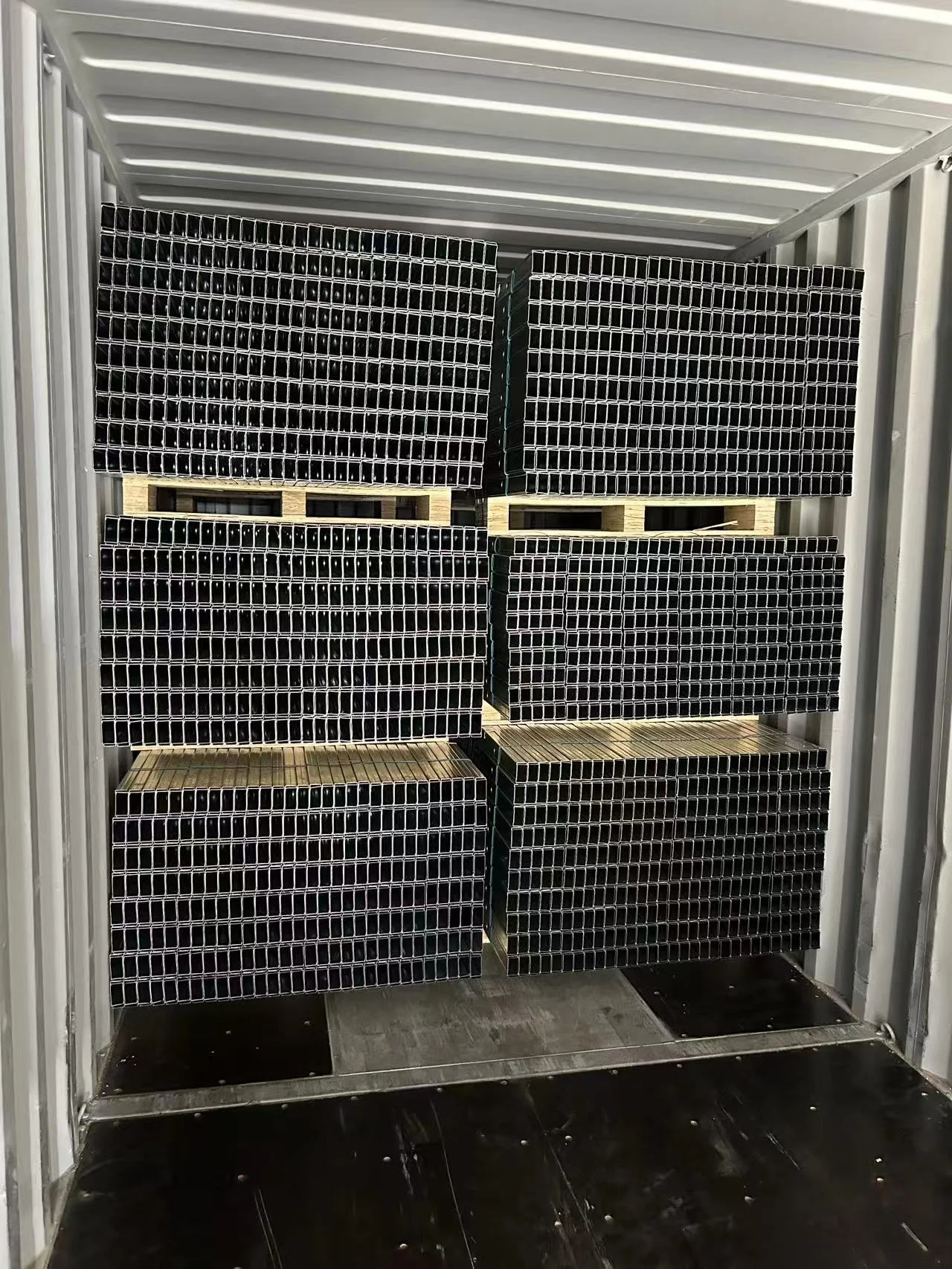
Loading images are provided to show the track-loading subject for reference. They do not state a loading capacity, shipping weight, or handling limit. For transport and site handling, follow the arrangements applicable to the order and the requirements of the receiving location. Keeping product bundles identified during unloading and storage can also help teams distinguish the selected materials before installation.

Track loading

Track loading
Accessories
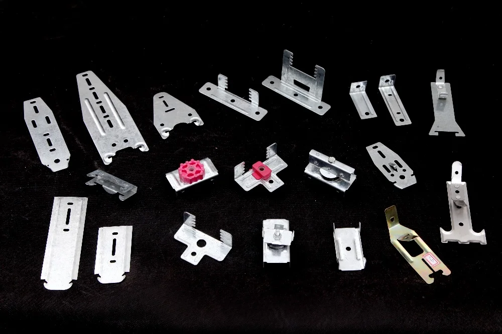
An accessories image is included as a visual reference. No accessory names, compatibility details, or package contents are specified here, so confirm any required accompanying components separately against the project documentation and order details. Keeping accessories and track selections coordinated supports clearer procurement and installation planning without assuming that unlisted items are included.